My adventures with a Raspberry Pi and Arduino programming

Archive for the ‘gpstxrx’ Category

Joystick controller and Menu system

I purchased a SparkFun Thumb Joystick and have just gotten around to making it work. Works a treat. Gives two analog outputs – one vertical, one horizontal – and a digital output for the stick being depressed like a button.

I’m now creating a library to manage a Menu system using the joystick. The menu system will support 16×2 monochrome parallel LCD screens, like the one I just got working.

The idea being you define different menu levels with options, and child menu items. Selection can be enabled or disabled. Selecting a parent menu item shows the children, moving left and right to highlight an item, depressing the button to select.

This will be a generic menu system that will have inbuilt support for the thumb joystick, but will also allow integration with other input systems.

I’m going to use this on the instructor’s receiver for my D of E group radio tracker project. You’ll be able to monitor multiple teams and use the menu system to show their positions, navigate to them, or view recent status information like location, last report time, distance, speed and so on.

Once I’ve got this working I’ll post a video of an example. Wish me luck!

LCD display working finally

Finally got around to getting my display working. I had thought I had a broken display but turns out that although Arduino analog pins can be configured to be digital pins, that won’t work with standard parallel mode LCD displays. Plugging all 6 pins to digital works fine.

Power usage stats (LCD + Arduino pro mini 3.3V):-

  • LCD backlight, no text – 3.69 mA
  • LCD backlight, 16×2 text – 3.70 mA
  • No LCD backlight, 16×2 text – 0.71 mA

So no prizes for guessing what mode I’ll have it in most of the time! I’ll have it off (no displayed text, no backlight)

Eye SPI Arduino…

I’ve been toying with how to handle multiple peripherals that require Serial. Up until now I’ve used the Software Serial library on Arduino, and have resorted for my SD card logger to use the hardware serial.

But is there a better way…

Maybe…

Lets have a look at the comms options:-

Part Hard Serial Soft Serial SPI I2C
ArduLogger V3 Y NO YES [0] YES [0]
GPS – GP635T Y Y NO NO
GPS – UBlox 6M module Y Y NO NO [1]
3DR Radio Y Y NO NO
LCD – Hitachi 44780 Y Y NO [2] NO

[0] ArduLog software only, not the SparkFun OpenLog software. Oh and you need to modify the code yourself to add support!
[1] The compass on the UBlox does have I2C SCL and SDA lines, but not the GPS
[2] It is possible to use a register to drive the LCD. May be possible to cleverly link this to an SPI interface

Hmmm… So maybe not then… Although of course nothing stopping me using interface circuitry to make all the above work, but it would probably add to the number of IO lines used, not reduce them!

Speaking of IO lines used, I’m currently using these:-

  • ArduLogger – 2 (hardware serial)
  • GP635T – 3 (2x soft serial, 1x power mosfet on/off)
  • 3DR Radio – 3 (2x soft serial, 1x power mosfet on/off)
  • LCD – 6
  • TOTAL: 14 (Arduino Pro Mini V3 I use has 22 pins that can be used for digital IO – 4 of these are optionally SPI, and another two optionally I2C)

I’ll keep a watching brief on using SPI though – could potentially be useful, and allow me to ‘off board’ a lot of serial comms in future.

[UPDATE 26 MAY 2015]

You can buy ICs that act as an SPI to multiple UART convertors each with a 64 byte FIFO queue. The chip model for two output UARTs (up to 4MBit/s!) is

SC16IS752IBS and is documented at http://www.nxp.com/documents/leaflet/75015676.pdf. This product also has some GPIO ports, so could theoretically externalise all my IO (including LCD) if I really needed to.

Hobbytronics ArduLogger V3 and Arduino pro mini circuit…

I’ve got a nice simple working circuit for my ArduLogger V3 board. Re-jigged it just now to minimise the number of wires. Image below for your edification:-

Ardu Logger V3 and Arduino Pro Mini

Ardu Logger V3 and Arduino Pro Mini

Remember too, when using a solderable breadboard (from SparkFun) of the same size, the logging sd card board will rotate 180 degrees, and sit below the breadboard rather than sticking out. A nice compact logging circuit.

I’ve got some test software that simulates logging GPX (XML) format GPS based track information to the SD card every couple of seconds. Sample SD card append code is available on my GitHub page.

Connect the FTDI to the pins (on the right of the breadboard, above) to your computer, and you’re away!

BE AWARE: When programming the board, remove the ArduLogger breakout from the circuit, else it interferes with serial communication to the Arduino pro mini. Once reprogrammed, disconnect the FTDI cable, add the ArduLogger back in, then reconnect the FTDI (to power the circuit). Alternatively power the breadboard directly.

Note on wires above:-

  • Blue wire links ground on the logger to the Arduino
  • yellow, orange, and grey wires take a circuitous route to link 5V with VCC on the Arduino
  • The position of the logger board next to the Arduino automatically lines up and connects TX and RX pins (and RST)

The sharp eyed among you may have noticed the Arduini is a 3.3V 8MHz variant, whereas the power pin on the logger says 5V. You can run 3.3V through here quite happily.

Note that as previously mentioned, the ArduLogger board and the open logger software only works with Hardware Serial – software serial WILL NOT work. You have been warned.

Arduino Pro Mini power saving modes

There are many ways to save power on the Arduino board itself. I summarise these with power consumption numbers…

(more…)

Image

D of E Tracker project box component layout…

Here’s some radio project pics for you…

gpstxrx-part-assembled

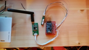
The first one, above, shows the partly soldered project. You can see the battery plug (top right of red solderable breadboard) which will go to my LiPo recharger circuit. You also see the 3DR radio airside module (left) and the mini GP-635T GPS unit (centre).

The aerial you see is the one that comes with the project. This is a WiFi aerial so will be getting replaced. Just waiting on a 433MHz compatible antenna to arrive.

gpstxrx-projectbox

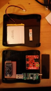
Here you see the project box layout. To the bottom of the picture is the bottom half of the project box. You see the GPS unit in the top part so its antenna doesn’t have a clouded view of the sky.

You also see the battery in the top half. This will be plugged in to the LiPo charging circuit (red, bottom picture, right hand side), which will also have a power cable going to the solderable mini breadboard with the Arduino mounted. (bottom left).

Again the radio (this time the ground side usb module) is mounted at the bottom. I’m investigating whether a short adapter circuit can be used to make use of the ground side module. Ideally I want a UART module like the airside one, but suppliers of the full pair of units give you one of each. (For about GBP 30).

The embedded SoC radio circuit though costs only GBP 2.62 from Mouser!!! So it may work out cheaper to take this, and the open source 3DR radio schematics (zip), and build my own UART on a PCB with this chip mounted.

Design rethinking

Something I’ve noticed is that the extra vertical pins on the Arduino (A4-A7) only just fit in the project box. This is without the non-permanent header block from the first image. I’ll remove the 4 extra analog pins as I’m no longer using them. This will mean I don’t have to solder the Arduino entirely to the breadboard – leaving it removable for use in other projects. (You can see the height of the Arduino in the top image because I use a header block to mount it.)

I may also remove the barrel jack from the LiPo charger to remove the possibility of someone plugging in both this and the USB cable!

I also need to check if the LiPo circuit has a voltage regulator. If so I’ll wire the output directly to the VCC rather than the RAW line of the Arduino. The Arduino’s voltage regulator is well known for being power hungry, so removing this will help overall power consumption.

I’ve toyed with the idea of modifying the LiPo charger to be a 1-2 Amp charger, but most USB sockets don’t support above 500mA so I think its easier to just make people wait 4 hours to recharge the battery and keep the power lower.

In the future I’d like to add a way to download an activity log. I may develop a Bluetooth app for this – but for now I’m happy with a live view of data.

More tracker power saving tricks…

I’ve now employed a bunch of tricks to reduce power consumption. Here’s what I’d done…

(more…)

GPS power savings tests

Turns out you can save a hulluva lot of power by carefully using a GPS unit…

(more…)

D of E radio tracker project progress update…

Managed to spend a bit of time playing with my gpstxrx project now I’ve finished writing NoSQL For Dummies! Made a lot of progress already…

(more…)

I2C and software serial and hardware serial working fine!

I’ve now got all communication channels working on the Arduino Pro Mini just as I had on the Raspberry Pi (aka Ralph) and the Gertboard…

(more…)