My adventures with a Raspberry Pi and Arduino programming

Archive for May, 2015

Eye SPI Arduino…

I’ve been toying with how to handle multiple peripherals that require Serial. Up until now I’ve used the Software Serial library on Arduino, and have resorted for my SD card logger to use the hardware serial.

But is there a better way…

Maybe…

Lets have a look at the comms options:-

Part Hard Serial Soft Serial SPI I2C
ArduLogger V3 Y NO YES [0] YES [0]
GPS – GP635T Y Y NO NO
GPS – UBlox 6M module Y Y NO NO [1]
3DR Radio Y Y NO NO
LCD – Hitachi 44780 Y Y NO [2] NO

[0] ArduLog software only, not the SparkFun OpenLog software. Oh and you need to modify the code yourself to add support!
[1] The compass on the UBlox does have I2C SCL and SDA lines, but not the GPS
[2] It is possible to use a register to drive the LCD. May be possible to cleverly link this to an SPI interface

Hmmm… So maybe not then… Although of course nothing stopping me using interface circuitry to make all the above work, but it would probably add to the number of IO lines used, not reduce them!

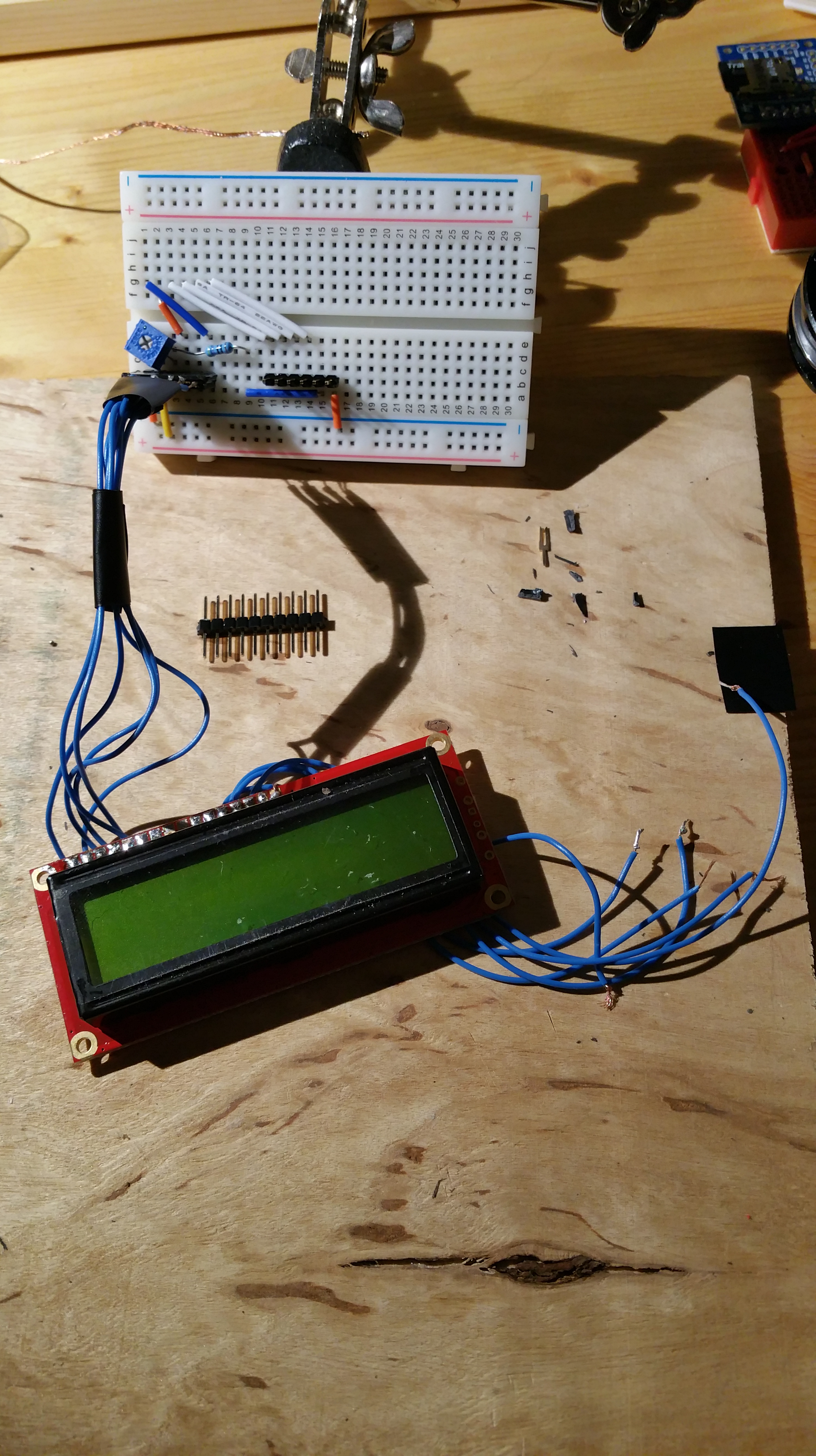
Speaking of IO lines used, I’m currently using these:-

  • ArduLogger – 2 (hardware serial)
  • GP635T – 3 (2x soft serial, 1x power mosfet on/off)
  • 3DR Radio – 3 (2x soft serial, 1x power mosfet on/off)
  • LCD – 6
  • TOTAL: 14 (Arduino Pro Mini V3 I use has 22 pins that can be used for digital IO – 4 of these are optionally SPI, and another two optionally I2C)

I’ll keep a watching brief on using SPI though – could potentially be useful, and allow me to ‘off board’ a lot of serial comms in future.

[UPDATE 26 MAY 2015]

You can buy ICs that act as an SPI to multiple UART convertors each with a 64 byte FIFO queue. The chip model for two output UARTs (up to 4MBit/s!) is

SC16IS752IBS and is documented at http://www.nxp.com/documents/leaflet/75015676.pdf. This product also has some GPIO ports, so could theoretically externalise all my IO (including LCD) if I really needed to.

Hobbytronics ArduLogger V3 and Arduino pro mini circuit…

I’ve got a nice simple working circuit for my ArduLogger V3 board. Re-jigged it just now to minimise the number of wires. Image below for your edification:-

Ardu Logger V3 and Arduino Pro Mini

Ardu Logger V3 and Arduino Pro Mini

Remember too, when using a solderable breadboard (from SparkFun) of the same size, the logging sd card board will rotate 180 degrees, and sit below the breadboard rather than sticking out. A nice compact logging circuit.

I’ve got some test software that simulates logging GPX (XML) format GPS based track information to the SD card every couple of seconds. Sample SD card append code is available on my GitHub page.

Connect the FTDI to the pins (on the right of the breadboard, above) to your computer, and you’re away!

BE AWARE: When programming the board, remove the ArduLogger breakout from the circuit, else it interferes with serial communication to the Arduino pro mini. Once reprogrammed, disconnect the FTDI cable, add the ArduLogger back in, then reconnect the FTDI (to power the circuit). Alternatively power the breadboard directly.

Note on wires above:-

  • Blue wire links ground on the logger to the Arduino
  • yellow, orange, and grey wires take a circuitous route to link 5V with VCC on the Arduino
  • The position of the logger board next to the Arduino automatically lines up and connects TX and RX pins (and RST)

The sharp eyed among you may have noticed the Arduini is a 3.3V 8MHz variant, whereas the power pin on the logger says 5V. You can run 3.3V through here quite happily.

Note that as previously mentioned, the ArduLogger board and the open logger software only works with Hardware Serial – software serial WILL NOT work. You have been warned.

LCD breadboard and cunning headers…

So I’ve been struggling with wires everywhere in my projects. I’ve determined now that I suck so bad at soldering tonnes of plain wires that I need a better solution!

What I’ve done is solder the wire to female (yes, female) breakaway headers.

Idea being that male 90 degree bend headers are easiest to get, so I should be able to put these on the underside of my solderable breadboards. If I use a couple of pins in rather than the outermost ones I can even hide part of the female headers, so not taking up any extra space in my projects.

All also means that if one component is faulty I can easily replace them. I can also use them across projects, or plug them straight in to a breadboard for prototyping.

This arrangement is shown in the below image. This shows a basic LCD circuit. The top rail (j 1-6) are the IO pins pins going to the Arduino. The bottom rail shows two sets of 6 headers (only one shown plugged in for visibility).

LCD attached to breadboard via female headers

LCD attached to breadboard via female headers

I’ve kept the same numbers on the breadboard as on the LCD (left to right pins on top of the LCD). Thus it’s easier to remember. This also allowed me to get my resistor in there too.

The blue square on the left is a small breadboard potentiometer (variable resistor). Note I’ve put the LCD backlight pin (a 16) to ground, as I’m not using the backlight.

The circuit shown was taken from a PighiXXX ABC diagram.

This now gives me a low cost and re-usable way to plug various components in and transfer them between projects. I can do the same to SMD components, like a female USB A socket, like below:-

Female USB A with headers

Female USB A with headers

Pretty cool… Not bad for a few minutes work!

ArduLog OpenLog and Software Serial…

I’ve been playing around with a great SD card logging unit from Hobby Tronics. This is a slightly improved version (and cheaper!) of the SparkFun OpenLog unit.

Software Serial has failed me on this piece though. You absolutely must use the standard hardware serial (Serial.println() ) functions in order to not lose data. Even with large multi-second delays and very little information being transferred, the Arduino Software Serial library failed to keep up.

This is unusual, as I’ve found the Software Serial library very reliable for use with GPS and 3DR radios’ serial interfaces.

I’ve successfully used the setup() routine to specify the file I want to save to. This required a bit of hackery. To send a Ctrl+Z character in Arduino (required for setting up the open log in command mode) you need to do the following in code:-

 Serial.print((char)0x1A); // Ctrl + z
 Serial.print((char)0x1A);
 Serial.print((char)0x1A);
 delay(1000);
 Serial.println("append " + file); // tell open log to append to a named file (file created if it doesn't exist)
 delay(1000);
 logGpx(file,team,now); // my customised logging setup function

Those delay() calls probably aren’t strictly required, but they don’t slow down my app either.

Note that char 0x1A is a hexadecimal number for ASCII character 26 (the A is the 10th character in a sequence, the 1 in the second column means 1×16 (base 16), thus 10 + 16, which is character code 26. ASCII character 26 is the same as Ctrl+Z in a terminal in Windows CoolTerm, which is the required character for entering and leaving command mode in OpenLog.

I’m using the XML based GPX format to write updates. In future I’m going to hook this up to a GPS, so it makes sense to use this format rather than NMEA as it can easily be read by online and desktop tools. You could use KML instead (Google Earth format).

I wonder how much current this little device draws?…

Power usage of just the memory card (doesn’t include the Arduino itself):-

  • During command mode, up to 12mA
  • During normal standby operation, 1.57 mA
  • During writing data, anywhere from 6.5 to 11.5 mA, averaging approx 7.8mA

Tracker project todos…

Just a quick list for my own needs…

Things already done:-

  • Proven transmitter sends valid GPS tracking data to receiver on computer
  • Built prototype transmitter and tested in the field
  • Integrated GPS, 3DR radio, Li-po charger, Li-po battery, Arduino solderable breadboard in to an enclosure
  • Tested power saving mode (7 – 15 days charge possible!)
  • Created very basic symmetric cryptography routines

Things to do next:-

  • Get route logging software working, preferably with GPX file output (OpenLogger on HobbyTronics ArduLogger platform with micro SD card)
  • Range test air to ground module outside on maximum power settings, continuous transmit
  • Investigate 3DR circuit to see if its possible to make own PCB cheaper (and integrate whole device in one half eurocard PCB)
  • Get LCD display working on protoboard
  • Get Joystick working for basic menu items on same protoboard
  • Test multiple transmitters with one receiver (including testing using ‘air’ unit for receiver, and receiving multiple signals on same receiver)
    • If can’t use air module, use usb to serial circuit for ground module (might be fun to try anyway…)
  • Test 3DR radio LBT (Listen Before Transmit) mode
  • Test encrypted messaging
  • Develop own binary format for messaging (C language struct?)

Recent purchases…

I’ve made a couple of recent purchases after considering the full scope of my project.

Firstly I’ve bought another SparkFun 16×2 LCD module, and this time I won’t ruin it with a soldering iron by accident!!!

This LCD will be used in the D of E supervisor’s receiver module. I’ve also developed a user interface and set of menus so you can navigate through and track multiple teams, find your own position, edit settings, and even navigate to a selected team. (distance, bearing).

In order to drive this though I had to use some sort of interface. Several small buttons seemed a bit fiddly to add to the box, so I’ve opted for a PlayStation controller like Joystick! I can mount this on the project box next to the LCD. If you push this joystick down it also acts like a selection button, so I have left to right, and up to down navigation, and a selection button. Just like a standard modern GPS unit (but at a fraction of the cost).

Interestingly, SparkFun have stopped selling the black project box, now instead selling a clear one. That’s pretty awesome from a show-and-tell perspective! I can now show off the project, and see the power LEDs through the case. No need to drill LED holes that may leak in water.

I’ve also decided to buy a couple of micro SD interface cards – a ArduLogger device from a local supplier, but with the SparkFun OpenLogger software installed. This software is a bit more flexible, allowing you to name multiple files and either replace their content or append new content. Perfect for a receiver tracking multiple teams – you can have a GPX file for each day for each team. Great! I’ll also fit this on the transmitter so I can check the teams actual route later if they go out of signal line of sight. Not that I don’t trust them…

I also decided against bluetooth for a couple of reasons. Firstly, more complexity, space, and power usage for a very limited ‘download’ mode at the end of a walk. Also because I have a whopping 433MHz module already with a high baud rate! May as well re-use that to request and force an upload of an entire set of logs. They’re only a few KB for a day, so won’t take long at all to transmit.

Having two transceivers also brings the tantalising prospect of sending and receiving messages. A future ‘posh’ version of the transmitter may be a bigger battery, and LCD screen, and another joystick – so the team can send progress reports and receive information from their supervisors. E.g. ‘get off the mountain – crazy weather coming!’

I’ve also found a cheap supplier in Singapore for my Arduino Mega boards. More on that in another post. They’re approx GBP 1.80 each! Great if you want to make a lot of modules.

For my next trick I’ll use a Dremel to cut holes in my project case so I can mount the components. More to follow!…