LCD breadboard and cunning headers…
So I’ve been struggling with wires everywhere in my projects. I’ve determined now that I suck so bad at soldering tonnes of plain wires that I need a better solution!
What I’ve done is solder the wire to female (yes, female) breakaway headers.
Idea being that male 90 degree bend headers are easiest to get, so I should be able to put these on the underside of my solderable breadboards. If I use a couple of pins in rather than the outermost ones I can even hide part of the female headers, so not taking up any extra space in my projects.
All also means that if one component is faulty I can easily replace them. I can also use them across projects, or plug them straight in to a breadboard for prototyping.
This arrangement is shown in the below image. This shows a basic LCD circuit. The top rail (j 1-6) are the IO pins pins going to the Arduino. The bottom rail shows two sets of 6 headers (only one shown plugged in for visibility).
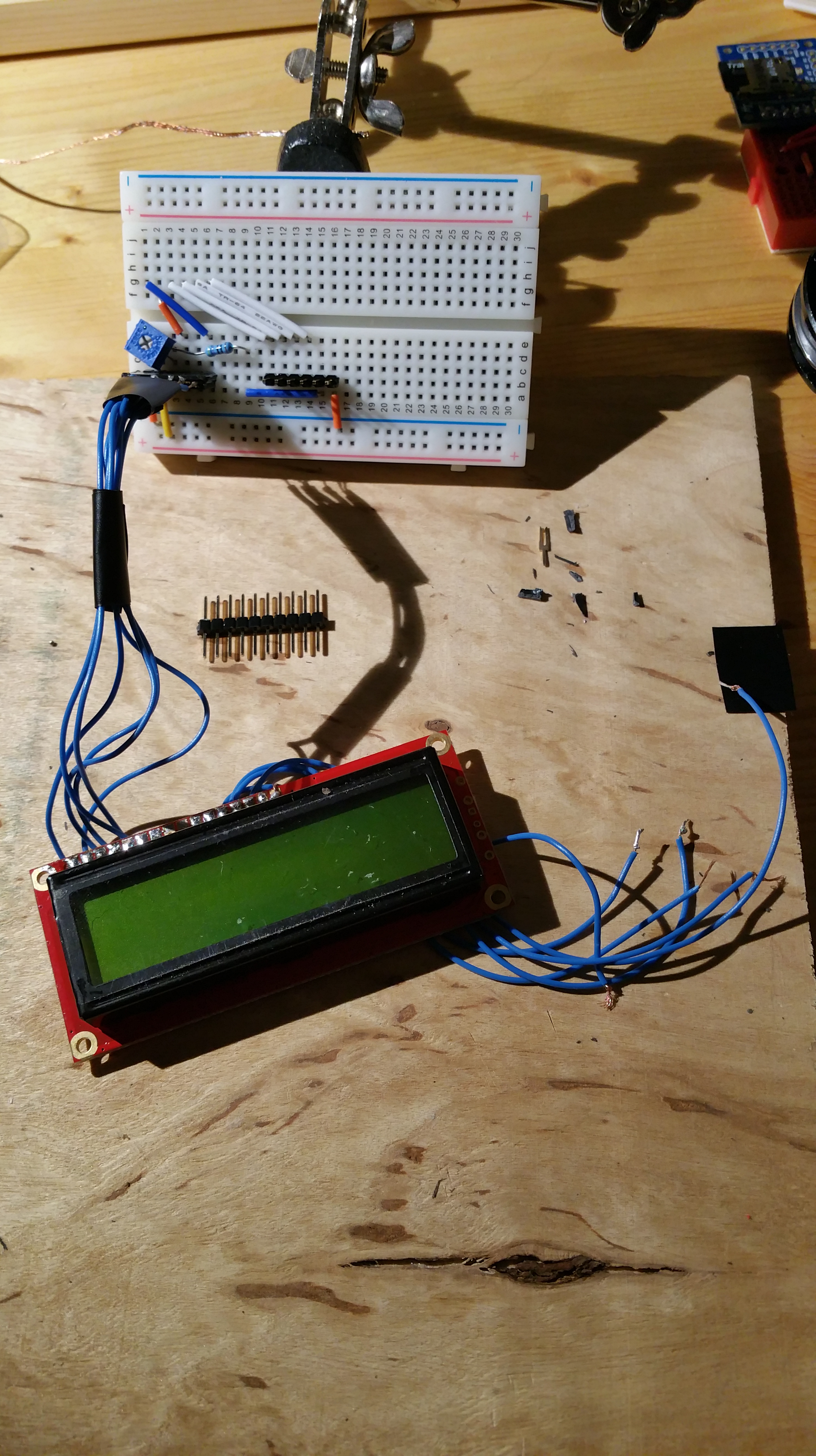
LCD attached to breadboard via female headers
I’ve kept the same numbers on the breadboard as on the LCD (left to right pins on top of the LCD). Thus it’s easier to remember. This also allowed me to get my resistor in there too.
The blue square on the left is a small breadboard potentiometer (variable resistor). Note I’ve put the LCD backlight pin (a 16) to ground, as I’m not using the backlight.
The circuit shown was taken from a PighiXXX ABC diagram.
This now gives me a low cost and re-usable way to plug various components in and transfer them between projects. I can do the same to SMD components, like a female USB A socket, like below:-
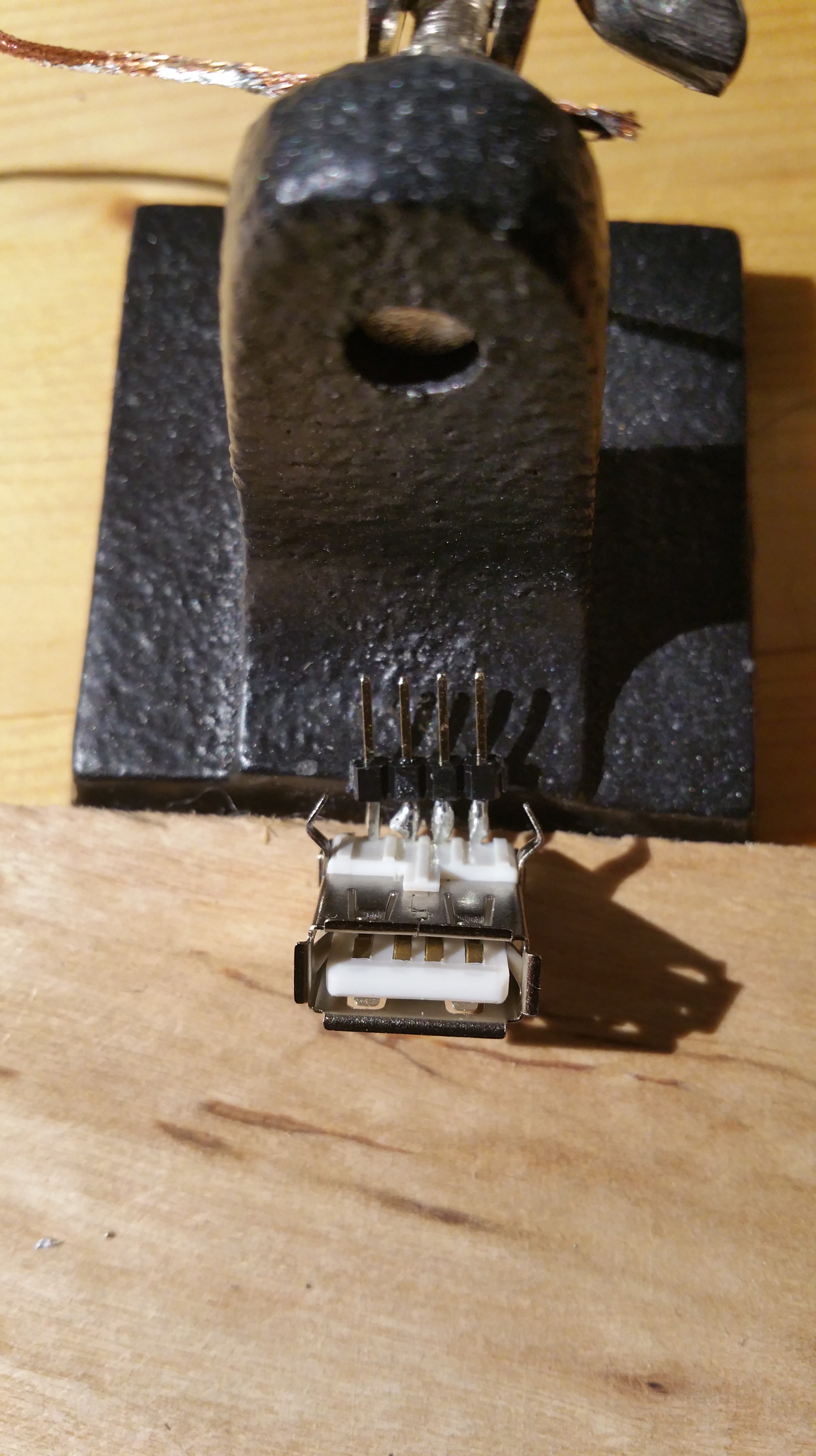
Female USB A with headers
Pretty cool… Not bad for a few minutes work!

Recent Comments